

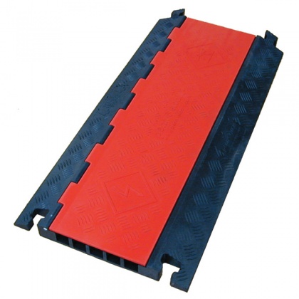
5 channels
PDCXT1891 is a cable/hose management system intended to reduce the possibility of damage to cables and hose lines that are subject to pedestrian and vehicular traffic. It is intended for temporary installations only and must be in accordance with all applicable electrical, building and safety codes. DO NOT use connectors or splices within this system.
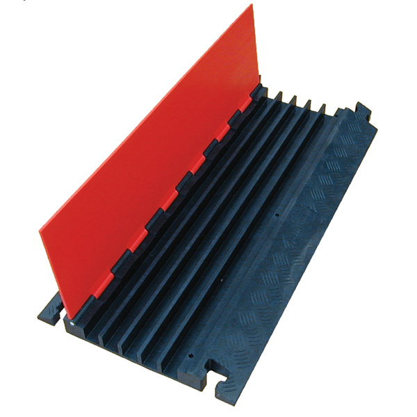
Photo 1: Lid hinged for a more rapid closure
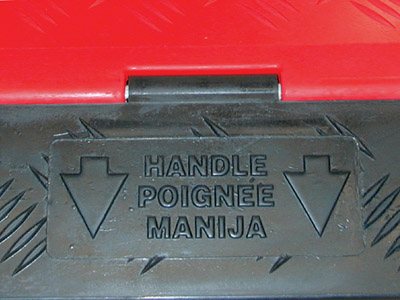
Photo 2: Back handle for easy transport
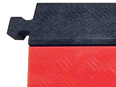
Photo 3: A "T" strong connection combines the modular sections
LOAD CAPACITY
The Cable/Hose Protection System has different load supporting capabilities depending on type of vehicle and temperature. Suitability must be verified by testing under actual conditions.
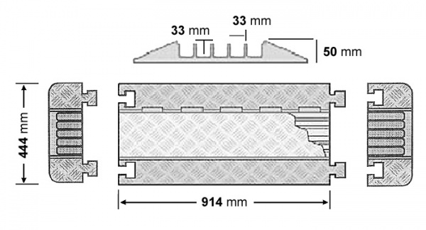
Ø max.: 33 mm
Minimum footprint: 175 x 439 mm
Max load per tire: 4,763 kg (21°C) - 2,948 kg (48°C)
Chemical resistance
Tested for compatibility with common motor oils, gasoline and diesel fuel. Limited resistance to brake fluids and other chemicals
Operating temperature: -40°C to 48°C.
CAUTION
- Keep various services, communications, fiuids and power separated. Limit a channel to one service type.
- Polyurethane is attacked by some chemicals. Always test a small amount for chemical compatibility before using and follow maintenance procedure.
- Vehicular traffic must pass over this system slowly and with caution.
- Caution misuse can cause electrical shock and injury.
- DO NOT use as work surface. NO CUTTING, NO DRILL NO HAMMERING.
- Use with momentary loads oniy, DO NOT place ladders, scaffolds, or any type of structure on the system.
- DO NOT place ladders, scaffolds, or any type of structure on the system.
- Avoid concentrated loads.
- Use only on a stable surface. Inclined surfaces, slippery surfaces and broken ground can cause injury.
- This system can be a trip hazard to pedestrian trafftic if they are unaware of its presence.
- Load-supporting capacity varies by type of loading conditions and environmental. conditions. The load capacity values are listed in the operating parameters. The load capacity decreased in warm environments.
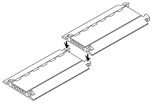
ASSEMBLY INSTRUCTIONS Photo 4
- Inspect areas for safety hazards.
- Assemble sections by aligning female over male connectors.
- Press with foot to secure female connectors to male connectors.
- Open cover and install cables down into channels.
- Close cover flush with base.
- Test installation for intended use.
- Periodically inspect installation.
HARDWARE by VALENTINI
Via Asti 84/A - 10098 Rivoli (TO) - ITALY
TEL.+39 0119594160
FAX +39 0119594166
info@syntaxnet.it
P.IVA 02571550017
Privacy and terms of use